Tooling Considerations for Plastic Part Design
In our previous blog we discussed various manufacturing methods for plastic parts. Although plastic parts can be manufactured by several methods, the main factor for the cost of manufacturing is always the mold unless 3D printing or machining is used. Simpler the mold, lesser the cost. In this blog, we are going to focus on plastic part design considerations for cost effective tooling and manufacturing.
TOOLING CONSIDERATIONS
The manufacturing cost per piece depends on mold cost, material, and cycle time. More complex the part design, more complex and expensive the mold. It also affects the cycle time. So, to reduce the cost per piece, mold should be as simplified as possible. Below are some things that should be considered while designing any plastic component to reduce cost & time.
WALL THICKNESS
Wall thickness of part decides the quantity of material and also the flow of material. Large wall thickness will result in more material and cycle time. Similarly, a very thin wall will require higher pressure and heat so that material does not solidify before filling the cavity, generally known as a short shot. The first step into an ideal plastic part design is to find optimal thickness and then maintain that thickness across all the sections. If the uniform wall thickness cannot be incorporated then the transition to different thicknesses should be gradual.
RIBS
Structural strength of plastic depends on the thickness of the plastic. Since we should maintain uniform wall thickness, ribs can be added to increase structural rigidity. Following points should be considered while adding ribs.
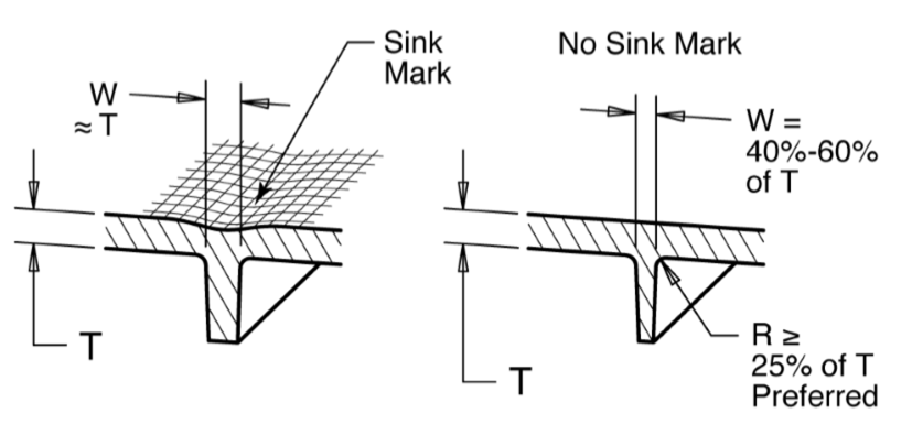
- The thickness of the ribs depends on the required strength but due to manufacturing constrains thickness of rib is generally kept as 50% to 60% of the wall thickness where the rib is attached. When molten plastic solidifies, it shrinks. It will pull the material towards the area where the rib is joined with base. Higher the thickness of the rib, larger the sink mark and it will look bad aesthetically.
Figure No. 1 Design Consideration for Avoiding Sink Marks (Image Courtesy: Stratasys)
- To minimize the sink, rib thickness should be reduced but thin ribs are difficult to fill. A flow simulation should be done to ensure the manufacturability of ribs.
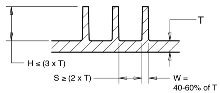
- The height of the rib should not be less than 3 times of base width. Rather than adding a tall rib, it is recommended to add multiple short ribs.
Figure No. 2 Design Consideration for Height of Ribs (Image Courtesy: Stratasys)
UNDERCUTS
Undercuts are any features that prevent the ejection of the molded part from a simple split mold. It requires complex tooling to manufacture these types of features and it increases the cost of the mold. Therefore, undercuts should be avoided as much as possible. But sometimes it is necessary to include these features e.g. for snapping. Even though undercuts can still be manufactured using side action sliders, collapsible cores, etc. it is expensive and increases cycle time. Following things can be considered while designing parts to avoid undercuts.
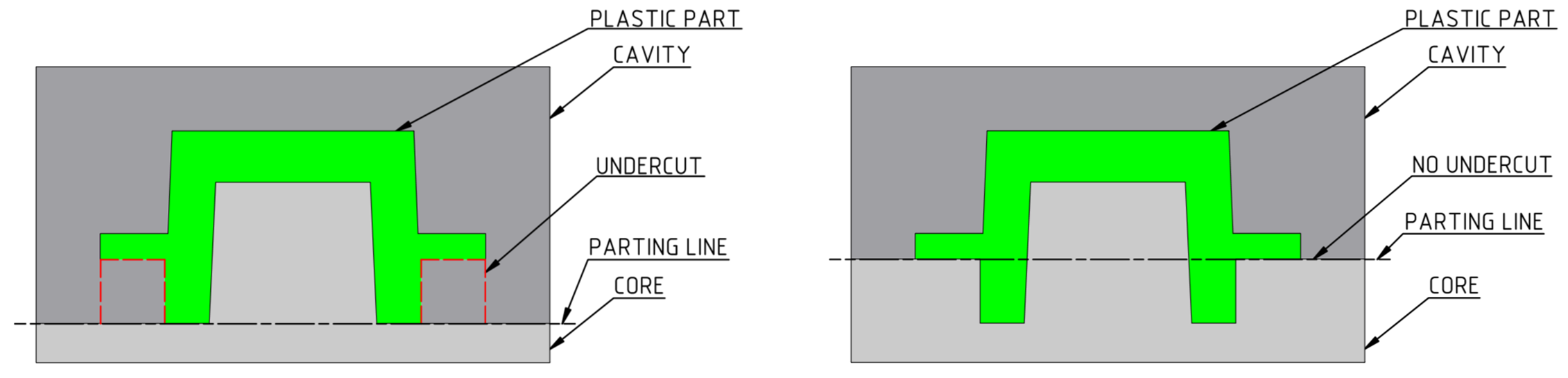
- Moving the parting line: Aligning the parting line such that it intersects the undercut. The undercut will then be removed
Figure No. 3 Eliminating Undercuts by Changing the Parting Line
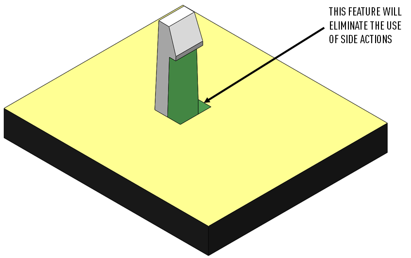
- Molding Shut Offs: Snap features or clip-on features are most likely to become an undercut. The mechanism itself cannot be eliminated but with the shutoffs, the undercut can be removed while manufacturing. Molding shut off just creates a cavity in the mold direction below the undercut removing the need for side actions.
Figure No. 4 Eliminating Undercut by making Shut-Off
- Changing the Design: Modifying the design of locking features such as threads or snap-fit in such a way that it cannot become an undercut is the most suitable approach.
SHRINKAGE
A certain percentage of shrinkage is expected in any plastic molding. As shrinkage cannot be avoided, the simple way the manufacturer overcomes it is to scale the model by the shrink percentage. Shrinkage percentage for each material is available, but the actual percentage of shrink depends on multiple factors such as type of plastic, the temperature of molding, cooling rate, size and shape of the part, features such as holes & slots, etc. When designing parts for assembly, consideration of shrinkage vital. Shrinkage can also cause problems for ejecting a part from mold. It can also result in voids as it pulls material inwards where the plastic is cooled.
Differential shrinkage can also result in warping. Warping reduces not only dimensional accuracy but also ruins aesthetic look and shape. The most common cause of warping is the change in thickness. That's why it is necessary to maintain uniform wall thickness or give a smooth transition to change in thickness.
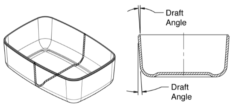
DRAFT
The ejection of the part from mold depends on the draft. A zero draft can result in difficult or no ejection due to shrinkage. It is recommended to add a minimum of 0.5 to 1 degree of the draft for non-textured surface & 3 to 5 degree of draft for textured surfaces. Drafts are only necessary in the direction of pull of mold. If the part is already shaped such that it can be removed easily from mold then there is no need to apply additional draft.
Figure No. 5 Draft Angle for easy Ejection of Part (Image Courtesy: Stratasys)
GATES
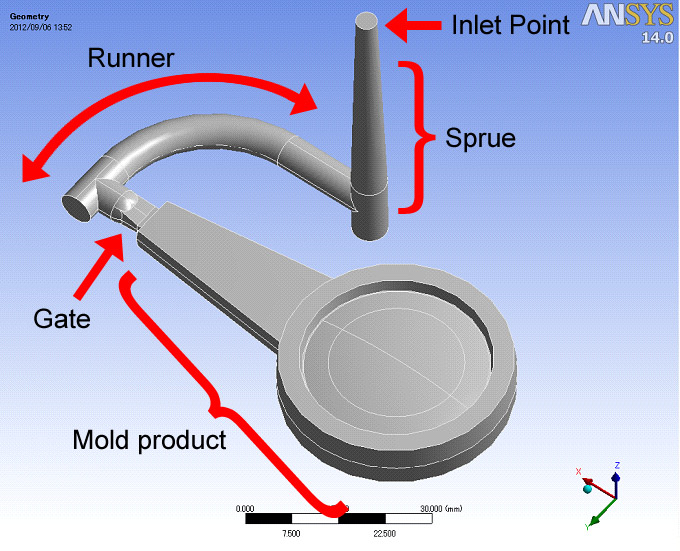
Gate is an opening from where the molten plastic enters into the mold. The location of the gate is critical because it ensures that the mold cavity is filled with plastic without voids. The location of the gate should be such that the material flows from a larger section to smaller section. Multiple gates can be added to reduce filling time and to ensure complete fill of the cavity. But there is a probability of knit lines where two flows collide with each other.
The molten plastic flows through the channels in mold known as runners. Runners are generally used in multi-cavity molds.
Figure No. 6 Gate, Runner, and Sprue with respect to Part
EJECTION
Ejection of the part from the mold is achieved with the help of ejection pins which applies force on the molded part. Easy ejection of the part depends on the draft angle, force of ejection, solidifying time for plastic, and size of the ejector pin. A mold release agent can be used to facilitate easy ejection. Time for ejection is also considered in cycle time, so reducing the ejection time will result in lower cycle time.
MOLD MATERIAL
The material of mold is one of the major contributors to the cost of molding. Injection molding molds can be made from Steel, Aluminum or Silicone.
Steel molds are used for large quantities and can be used for more than 500,000s cycles. They are also the most expensive due to expensive machining, heat treatment, and finishing processes.
Aluminum molds are used for batch production and cost less. Machining is easy, inexpensive, and requires less time than Steel molds. Aluminum also cools quickly and gradually so the cycle time also reduces. The maximum shot life of an Aluminum mold is less than 100,000 cycles.
Silicone molds are used for prototyping purposes only. They can be easily made without requiring any post-processing for surface finish.
TOOLS THAT HELP IN PLASTIC PART DESIGNING
CAD tools are used to design most of the plastic parts. Molds are also made using CAD tools. For effective manufacturing, it is necessary to analyze part as well as mold. CAD tools offer following features that help in designing manufacturable plastic parts and mold.
- Undercut Analysis: Undercut analysis can be performed on the plastic part to determine areas that might prevent easy ejection of part. For undercut analysis, parting line and the direction of the pull are only needed.
- Thickness Analysis: With the help of thickness analysis, wall thickness can be evaluated. Maximum and minimum thickness can be identified. The change in thickness can also be determined with this tool.
- Geometry Analysis: It helps in identifying sharp edges and corners in the design. These can be easily removed.
- Draft Analysis: Based on the direction of pull and threshold value of minimum draft angle, the user can identify the faces where the draft angle is applied and where is missing or below the minimum value required.
Besides this, a Design for Manufacturability (DFM) analysis can also be run on the plastic part to determine problems that can affect the molding. DFM tools work with CAD files and consider the standard practices followed in the manufacturing industry to perform analysis. Custom rules can also be set for incorporating the limitations of a manufacturer of your choice.
Another operation for better manufacturing is to run a flow simulation of plastic in the mold cavity. This can help in evaluating the size and locations of gates and runners. It can also help in identifying the possibilities of short shots due to thin sections.
IMPROVIANS TAKE
Plastics are the ever-evolving industry that will grow further in the future. Plastic parts cannot be eliminated from day to day consumer life. To stay ahead in the market, it is necessary to design plastic parts that are inexpensive and quick to manufacture. This can be only achieved when the tooling and manufacturing considerations are taken into account while designing the part. There are multiple tools available that can help in designing better parts. The designer has to be very familiar with the plastic molding or should be closely associated with an experienced manufacturer. Rather than spending extra time and money on costly reworks, it is better to partner with someone expert in the domain. At Improvians, we can help you with all your plastic product design requirements.
- https://www.nicoletplastics.com/resources/blog/8-factors-in-plastic-part-design-for-manufacturability/
- http://injectionmolding.blog.quickparts.com/
- https://www.ptonline.com/articles/best-methods-of-molding-undercuts
- https://www.custompartnet.com/wu/InjectionMolding